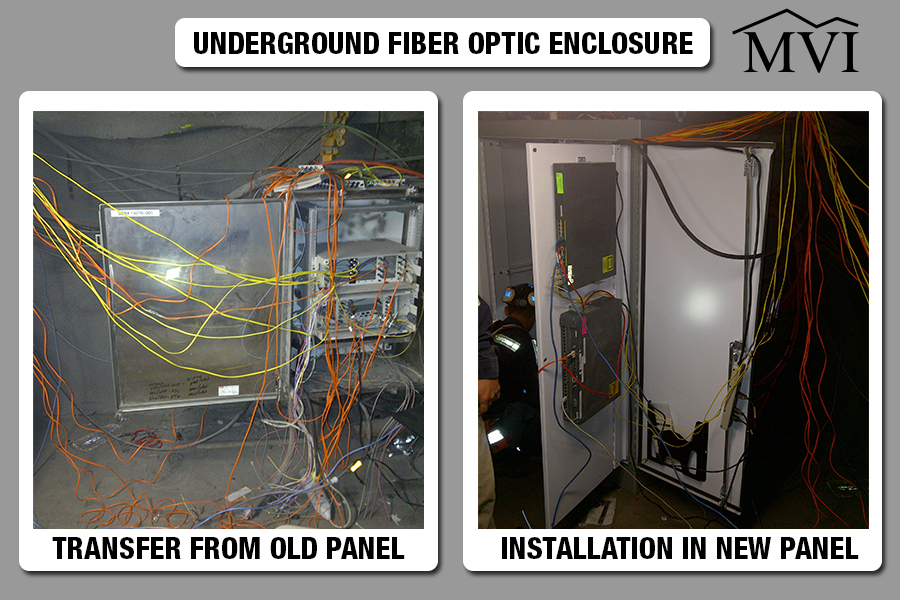
MVI has recently successfully designed, built, installed, and commissioned an elevator control system for use in an underground coal mine located in southwest Pennsylvania. MVI personnel also participated in the ANSI 17.1 testing for the newly installed elevator.
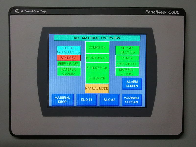
The control system for this installation uses a PLC to both control the operation of the elevator and to assist in the troubleshooting process should any problem occur. Large easy-to-read touch screens provide operator interface to check the operation of all critical components. Power for this installation was provided by a four quadrant DC drive, but MVI is also very familiar with AC variable frequency drives.
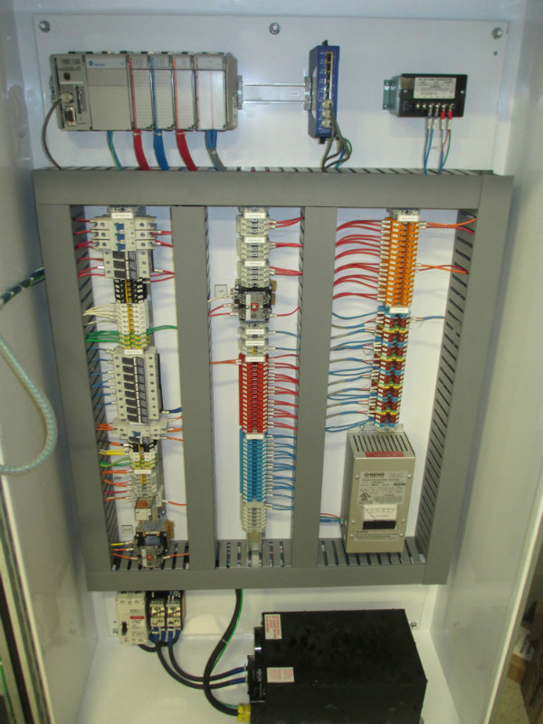
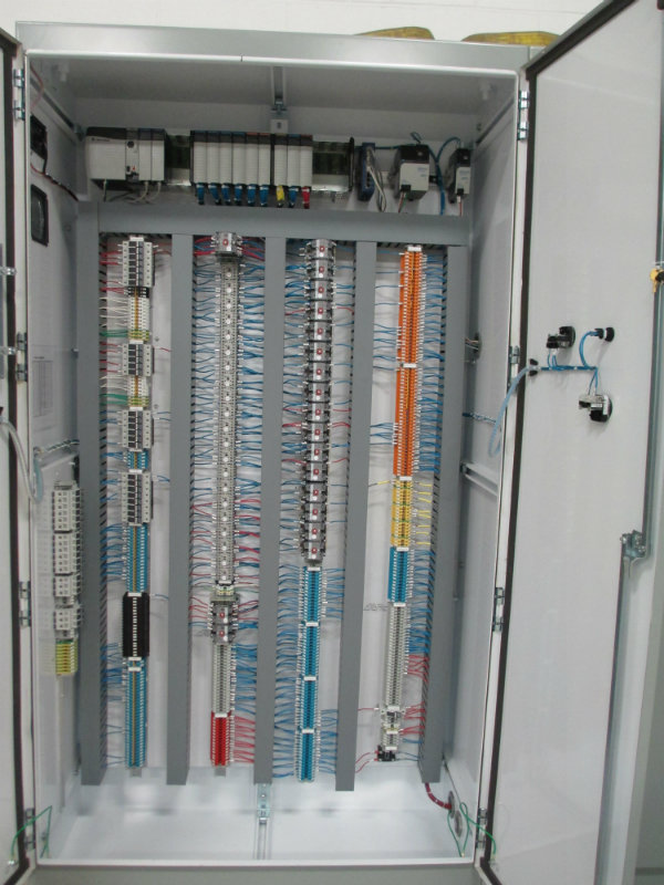
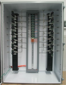
All MVI control panels are designed and assembled at our facility in Morgantown, WV.
All PLC programming is also done in-house at the same facility.

Whether for a complex installation, such as an elevator, or for a simple lighting panel, all control panels are fully tested in our facility before they are delivered to the customer site.

MVI is a UL Certified 508A panel shop. In addition to designing and building custom control panels suited to your application, we can supply control panels for critical applications such as elevators, cranes and hoists. If desired, any control panel that we design and assemble can display the UL label.

Generator-Panel_IMG_3753_1-11Main-and-Drive-Panel_IMG_3824_1-1


If properly lubricated, anti-friction bearings can last a very long time. However, as the size and number of bearings on a piece of equipment increases, proper bearing lubrication can be a very labor-intensive job.

Working with our customer, MVI has developed a PLC-controlled automatic greaser panel (AGP) that will dispense the proper amount of grease to each bearing, regardless of its size from a central location.
All that is needed is a supply of grease, a grease pump, and a single phase 120 VAC supply.

The PLC can be programmed as to how often each bearing is lubricated and how much grease is pumped into that bearing. In that way each bearing, regardless of its size, will be properly lubricated. In addition, there is no wasted lubricant and no greasy rags to dispose of.

With the AGP each bearing, regardless of its location, can be safely lubricated while the equipment is in operation. Lubricating a rotating bearing allows the lubricant to be distributed evenly throughout the bearing. Properly lubricated bearings extend component life, resulting in fewer breakdowns, which in turn results in reduced replacement and maintenance costs.

This system is available in a wall-mounted NEMA12 enclosure and can accommodate up to 20 grease ports. Other configurations are available upon request. Our AGP is also approved for underground use in the State of Pennsylvania.

IMG_6153_1-233x300


We were approached by one of our customers to assist them with upgrading one of their underground fiber optic networking hubs. Communications in the mine environment is critical, especially when monitoring of fans, pumps, belts, and diesel systems require constant uptime; if any of these go down, even for a short time, workers sometimes have to be evacuated, leading to costly production down time. We approached this project with the following goals:

  • Clean up the customer’s existing installation and migrate it to a new, larger enclosure
  • Create an environment that will be easier for someone not intimately familiar with the system to perform troubleshooting duties
  • Allow for future growth of their fiber optic network to be terminated and patched in the enclosure

After finalizing the installation, our customer was very satisfied. We were able to work closely with them to achieve their objective of a well organized, expansion-ready fiber optic hub.


UG-Fiber-Enclosure-Transfer-5 UG-Fiber-Enclosure-Exterior-4 UG-Fiber-Enclosure-Interior-2 UG-Fiber-Enclosure-Incoming-fiber-3 UG-Fiber-Enclosure-Interior-1


The objective was to create an underground railroad traffic control system for unattended areas in a large mine.

This system consists of a light pod to be mounted at each end of a “block tunnel.”  The light pod would have a green (proceed) and red (stop) signal, so that approaching vehicles would know whether or not there was another vehicle in the tunnel; vehicles entering the tunnel are to manually trip a switch, thus sending a signal to both light pods in order to direct traffic flow.

The light pods and their switches are connected to a custom electrical enclosure (one at each end of the block tunnel) that houses switching relays and a Programmable Logic Controller (PLC).  These two PLCs communicate to each other in order to make sure that both light pods are displaying the same information, thus avoiding having multiple vehicles in the tunnel at the same time.

The objective was achieved, and several of these Pennsylvania Department of Environmental Protection Approved systems are in service in mines across Southwestern PA, with more being added as the mines expand.


The objective was to create a rock dust tank system at a mine site in order to facilitate receiving material from a transport truck, storage of the rock dust on the surface, and delivery of material underground to a waiting rock dusting pod.

Because proper applications of rock dust can prevent the propagation of coal dust explosions, Mine Safety and Health Administration regulations requires that all areas of a coal mine that can be safely traveled must be kept adequately rock dusted to within 40 feet of all working faces. Due to the large quantity of rock dust required on a daily basis for usage in the mine, Mon Valley Integration was tasked by our customer to create a system that would not only store a large quantity of dust, but would able to deliver it underground on demand in a safe and efficient manner.

This system will allow truck drivers to unload their payload into the surface rock dust tanks safely by providing status lights and selector switches to disable the system while material is being transferred.

This system is self-monitoring, with Programmable Logic Controller (PLC) monitoring for all aspects of the process: delivery, storage, and transfer. PLC systems are located on the surface and underground to enable remote monitoring, control, and troubleshooting.

By collaborating with the customer, the objective was achieved. With a successful installation, the Rock Dust Control System became a valuable addition to the client’s facility.

rdt-04rdt-5rdt-02rdt-03


Cost Effectiveness and Efficiency through Power System Analysis

sample-time-current-curve

At a large underground mine utilizing two power sources, mine personnel wanted to use the second source to feed some of the mining loads that were being supplied by the first source of power. The first source was supplied from the electric utility and the second source at the remote end of the mine.

Mon Valley Integration (MVI) was presented with the opportunity to answer the questions: What loads do we supply from the first source and what loads to we supply from the second source to remain within contractual guidelines with the utility and at the same time, provide the best voltage regulation for our mining loads?

The traditional approach to finding a solution would be “trial and error.” During a scheduled power outage, you would open a line switch and connect the second power source to the de-energized portion of the distribution system in hopes of not receiving any penalties from the power companies for over or under utilization. You will not know if there are penalties until the power bill is received the next month. If there are penalties, a second scheduled power outage and re-allocation of the power distribution must be completed. This process is not efficient or cost effective.

Through the use of ETAP, MVI is able to model the entire system, creating a one-line diagram of the system which will conduct a load flow analysis, short circuit analysis and relay coordination studies.


Power allocation and re-allocation can be simulated with just a few key strokes with results in just a few minutes instead of months and utility loading is verified to make certain there are no utilization penalties. In addition, voltage regulation and relay coordination can be done based on the chosen method.

MVI can model any power system to help Owner/Clients determine any “What If” scenario without the expense and wasted time of trial and error.